
Description
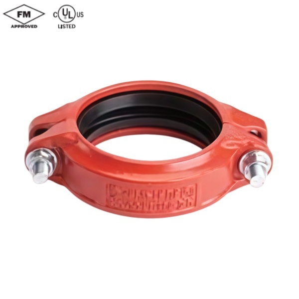
-Angle-Pad Design-
The Model GKS is an angle-pad design standardrigid coupling for moderate pressure piping servicesincluding fire mains,long straight runs and valueconnection.The angle-pad design allows the couplinghousings to slide along the bolt pads when tightened.Theresult is an offset clamping action which provides a rigidjoint which resists so-called 'snaking'of a long straight run.Support and hanging requirements correspond to ANSIB31.1,B31.9 and NFPA 13.
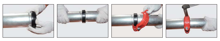
With the removal of only one bolt you can make a fastand easy 'swing-over'installation.
Sizes available:32mm-400mm/1-1/4“~16”Working Pressure:Up to 20 bar/300 psi
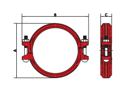
| Nominal Size mm/in | Pipe O.D. mm/in | Max.Working Pressure Bar/PSI | Max.End Load KN/Lbs | Axial Displacement mm/in | Dimensions | Bolts Size mm/in | ||
| A mm/in | B mm/in | C mm/in | ||||||
| 25 | 33.7 | 20 | 1.80 | 0-1.6 | 56 | 96 | 47 | M10×55 |
| 1 | 1.327 | 300 | 405 | 0-0.06 | 2.20 | 3.78 | 1.85 | 3/8×2-1/8 |
| 32 | 42.4 | 20 | 292 | 0-1.6 | 64 | 105 | 47 | M10×60 |
| 11/4 | 1.669 | 300 | 656 | 0-006 | 2.52 | 4.17 | 1.85 | 3/8×2-3/8 |
| 40 | 48.3 | 20 | 3.79 | 0-1.6 | 69 | 113 | 47 | M10×60 |
| 11/2 | 19 | 300 | 852 | 0-006 | 2.72 | 4.45 | 1.85 | 3/8×2-3/8 |
| 50 | 60.3 | 20 | 5.91 | 0-1.6 | 88 | 122 | 47 | M10×60 |
| 2 | 2.375 | 300 | 1327 | 0-0.06 | 3.46 | 4.80 | 1.85 | 3/8×2-3/8 |
| 65 | 73 | 20 | 8.66 | 0-1.6 | 100 | 137 | 47 | M10×70 |
| 21/2 | 2875 | 300 | 1945 | 0-0.06 | 394 | 5.39 | 1.85 | 3/8×2-3/4 |
| 65 | 76.1 | 20 | 9.41 | 0-1.6 | 100 | 137 | 47 | M10×70 |
| 21/2 | 3 | 300 | 2114 | 0-006 | 3.94 | 5.39 | 1.85 | 3/8×2-3/4 |
| 80 | 88.9 | 20 | 12.84 | 0-1.6 | 116 | 154 | 47 | M10×70 |
| 3 | 3.5 | 300 | 2885 | 0-1.7 | 4.57 | 6.06 | 1.85 | 3/8×2-3/4 |
| 100 | 114.3 | 20 | 21.22 | 0-4.1 | 142 | 188 | 52 | M12×75 |
| 4 | 4.5 | 300 | 4769 | 0-0.16 | 5.59 | 7.40 | 2.05 | 1/2×3 |
| 125 | 139.7 | 20 | 31.70 | 0-4.1 | 170 | 219 | 52 | M12×80 |
| 5 | 5.5 | 300 | 7124 | 0-0.16 | 6.69 | 8.62 | 2.05 | 1/2×3-1/8 |
| 125 | 141.3 | 20 | 32.43 | 0-4.1 | 170 | 219 | 52 | M12×80 |
| 5 | 5.563 | 300 | 7288 | 0-0.16 | 6.69 | 8.62 | 2.05 | 1/2×3-1/8 |
| 150 | 159 | 20 | 41.06 | 0-4.1 | 196 | 244 | 52 | M12×80 |
| 6 | 6.25 | 300 | 9229 | 0-0.16 | 7.72 | 9.61 | 2.05 | 1/2×3-1/8 |
| 150 | 165.1 | 20 | 44.27 | 0-4.1 | 197 | 244 | 52 | M12×80 |
| 6 | 6.5 | 300 | 9950 | 0-0.16 | 7.76 | 9.61 | 2.05 | 1/2×3-1/8 |
| 150 | 168.3 | 20 | 46.00 | 0-4.1 | 199 | 246 | 52 | M12×80 |
| 6 | 6.625 | 300 | 10340 | 0-0.16 | 783 | 9.69 | 2.05 | 1/2×3-1/8 |
| 200 | 219.1 | 20 | 77.97 | 0-4.1 | 262 | 322 | 66 | M16×120 |
| 8 | 8.625 | 300 | 17524 | 0-0.16 | 10.31 | 12.68 | 2.60 | 5/8×4-3/4 |
| 250 | 273 | 20 | 121.05 | 0-4.1 | 325 | 400 | 66 | M20×170 |
| 10 | 10.75 | 300 | 27206 | 0-0.16 | 12.80 | 15.75 | 2.60 | 3/4×6-7/10 |
| 300 | 323.9 | 20 | 170.39 | 0-4.1 | 376 | 468 | 67 | M22×190 |
| 12 | 12.75 | 300 | 38297 | 0-0.16 | 14.80 | 18.43 | 2.64 | 7/8×7-1/4 |
| 350 | 355.6 | 20 | 198.53 | 0-4.1 | 410 | 500 | 75 | M22×190 |
| 14 | 14 | 300 | 46150 | 0-0.16 | 16.14 | 19.69 | 2.95 | 7/8×7-1/2 |
| 400 | 406.4 | 20 | 259.30 | 0-4.1 | 459 | 550 | 75 | M22×190 |
| 16 | 16 | 300 | 60280 | 0-0.16 | 18.07 | 21.65 | 2.95 | 7/8×7-1/2 |