
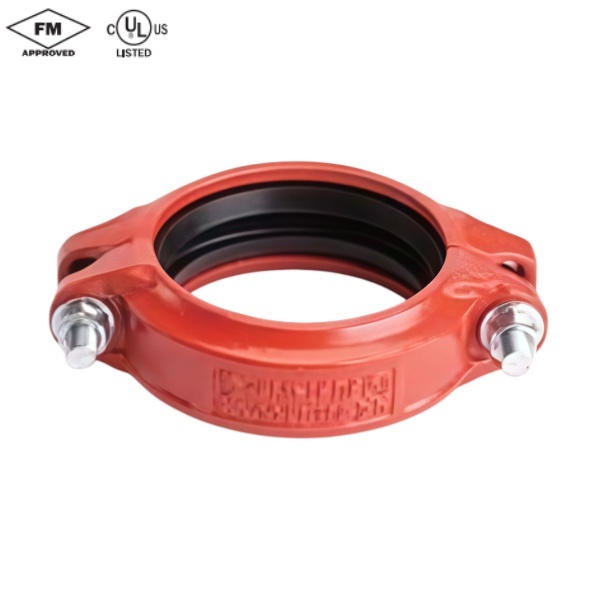
Description
-Angle-Pad Design-
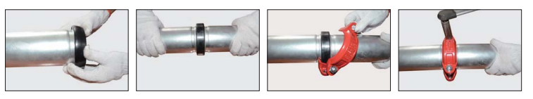
The Model 1512 is an angle-pad design standardrigid coupling for general piping applications where rigidityis required including value connections,mechanical rooms,fire mains and long straight runs.The angle-pad designallows the coupling housings to slide along the bolt padswhen tightened.The result is an offset clamping actionwhich provides a rigid joint that resists flexural andtorsional loads.Support and hanging requirementscorrespond to ANSI B31.1,B31.9and NFPA 13.
Sizes available:32mm-300mm/1-1/4“~12”Working Pressure:Up to 35 bar/500 psi
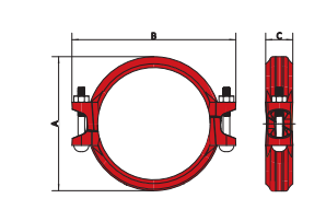
| Nominal Size mm/in | Pipe O.D. mm/in | Max.Working Pressure Bar/PSI | Max.End Load KN/Lbs | Axial Displacement mm/in | Dimensions | Bolts Size | |||
| A mm/in | B mm/in | C mm/in | No. | mm/in | |||||
| 32 11/4 | 42.4 1.669 | 35 500 | 2.92656 | 0-1.6 0-0.06 | 64 2.52 | 106 4.17 | 47 1.85 | 2 | M10×60 3/8×2-3/8 |
| 40 11/2 | 48.319 | 35 500 | 3.79852 | 0-1.6 0-0.06 | 69 2.72 | 113 4.45 | 47 1.85 | 2 | M10×60 3/8×2-3/8 |
| 502 | 60.3 2.375 | 35 500 | 9.842212 | 0-1.7 0-0.07 | 88 3.46 | 122 4.80 | 47 1.85 | 2 | M10×60 3/8×2-3/8 |
| 65 21/2 | 73 2.875 | 35 500 | 14.643240 | 0-1.7 0-0.07 | 100 3.94 | 142 5.59 | 47 1.85 | 2 | M12×70 1/2×2-3/4 |
| 65 21/2 | 76.13 | 35 500 | 15.683523 | 0-1.7 0-0.07 | 10164.00 | 142 5.59 | 47 1.85 | 2 | M12×70 1/2×2-3/4 |
| 803 | 88.9 3.5 | 35 500 | 21.394808 | 0-1.7 0-0.07 | 116 4.57 | 158 6.22 | 47 1.85 | 2 | M12×70 1/2×2-3/4 |
| 1004 | 114.3 4.5 | 35 500 | 35.367948 | 0-4.1 0-0.16 | 144.4 5.69 | 194 7.64 | 51 2.01 | 2 | M12×70 1/2×2-3/4 |
| 1255 | 139.7 5.5 | 35 500 | 52.8311874 | 0-4.1 0-0.16 | 171.6 6.76 | 230 9.06 | 52 205 | 2 | M16×85 5/8×3-1/3 |
| 1255 | 141.3 5.563 | 35 500 | 48.5910930 | 0-4.1 0-0.16 | 172 6.77 | 231 9.09 | 52 2.05 | 2 | M16×85 5/8×3-1/3 |
| 1506 | 165.1 6.5 | 35 500 | 66.3314920 | 0-4.1 0-0.16 | 198780 | 255 10.04 | 53 2.09 | 2 | M16×85 5/8×3-1/3 |
| 1506 | 168.3 6.625 | 35 500 | 76.6717233 | 0-4.1 0-0.16 | 200787 | 256 10.08 | 53 2.09 | 2 | M16×85 5/8×3-13 |
| 2008 | 216.3 8.515 | 35 500 | 126.6428465 | 0-3.2 0-0.13 | 265 10.43 | 334 13.15 | 63 248 | 2 | M20×120 3/4×4-3/4 |
| 2008 | 219.1 8.625 | 35 500 | 129.9429206 | 0-3.2 0-0.13 | 263.4 10.37 | 334 13.15 | 63 2.48 | 2 | M20×120 3/4×4-3/4 |
| 25010 | 267.4 10.527 | 35 500 | 193.5543502 | 0-3.2 0-0.13 | 317 12.48 | 396 15.59 | 65 2.56 | 2 | M22×190 7/8x7-12 |
| 25010 | 273 10.75 | 35 500 | 201.7445344 | 0-3.2 0-0.13 | 326 12.83 | 404 15.91 | 65 2.56 | 2 | M22×190 7/8×7-1/2 |
| 30012 | 318.5 12.539 | 35 500 | 274.5961718 | 0-3.2 0-0.13 | 375 14.76 | 464 18.27 | 65 2.56 | 2 | M22×190 7/8×7-1/2 |
| 30012 | 323.9 12.75 | 35 500 | 283.9863828 | 0-3.2 0-0.13 | 381 15.00 | 468 18.43 | 65 2.56 | 2 | M22×190 7/8×7-1/2 |